Remanufacturing, Refill the HP CP 2025 Black and Color Toner cartridges
Remanufacturing the HP CP 2025
Black and Color Toner cartridges
Feb 01, 2009
First released in April 2008, the CP 2025 series of color laser
printers are based on a 21ppm black and color, 600 Dpi engine. (3600 DPI
with RET). The 2025 cartridges are an all in one type cartridge that
consists of the toner supply, drum, and waste chamber. Like the CP-1215
these machines use an in-line, or single pass system. Also like the
CP-1215 all four cartridges are stacked in line front to back instead of
on top of each other as in older Hp single pass machines. See
Figures A and B. Because of this new machine layout, we will take a
moment and run through the printer theory before we get started. These
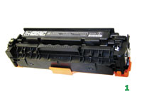
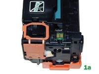
cartridges are basically a rectangular shaped cartridge that comes with
a toner seal and a snap-on drum cover across the bottom to protect the
drum. See Figures 1 and 1A. New machines ship with starter
cartridges rated for 1,200 pages so users will run out of toner fairly
quickly.
These cartridges also use chips that’s
should be replaced each cycle for the cartridges to have full
functionality.
The printers based on the CP2025 engine are
the:
HP Color LaserJet CP 2025n HP Color LaserJet CP
2025dn HP Color LaserJet CP 2025x HP Color LaserJet CP 2020 (Asia
only)
The cartridges used in these machines are the:
CB530A
(Black) 3,500 pages — $115.99 List* CB531A (Cyan)
2,800 pages — $114.99 List* CB533A (Magenta) 2,800 pages —
$114.99 List* CB532A (Yellow) 2,800 pages — $114.99 List* *
Pricing current as of December 2008.
HP-CP2025 Color
Printing Theory
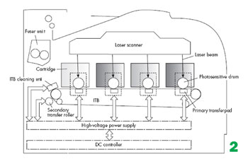
The Color toner cartridge printing
process happens in s series of stages or steps. For the purpose of this
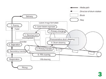
article, we will call them stages. Figure 2 shows the basic
layout of the cartridges and how they relate to one-another and the
printer. Note that while this is still a single pass system, the layout
is completely different from any previous Canon/HP machines. Figure 3
shows the complete image formation process
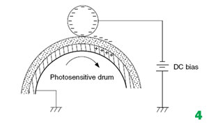
In the first stage, the Primary Charge
Roller (PCR) places a uniform negative DC voltage on the OPC drum
surface. The amount of the negative DC voltage placed on the drum is
controlled by the printer’s intensity setting. See Figure 4.
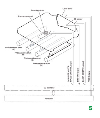
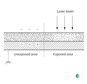
In the second stage, the laser beam is fired
onto a rotating mirror (called the scanner). As the mirror rotates, the
beam is reflected into a set of focusing lenses. The beam then strikes
the drums surface, reducing the negative charge and leaving a latent
electrostatic image on the drum. The areas where the laser did not
strike the drum will retain the higher negative charge. Technology has
advanced tremendously in these machines as there is one laser/scanner
unit for all four colors. The laser/scanner unit contains one scanning
motor and mirror with four separate lasers. See Figures 5 and 6.
The third or developing stage is where
the toner is developed on the drum by the developing section (or supply
chamber), which contains the toner particles. The development stage is
actually made up of two steps: toner charging, and the actual
development. In the toner charging stage, the toner stirring blade turns
inside the hopper. As it turns, friction causes a negative potential to
develop on the toner. In addition, a foam feed roller brings the toner
to the developer roller and also places a negative charge on the toner.
These two charges help ensure a uniform charge on the toner.
Once
the toner is properly charged, the toner will coat the developer
roller. The toner is also held onto and attracted to the developer
roller by another negative DC bias voltage. This voltage is controlled
by the printer’s intensity setting and causes either more or less toner
to be attracted by the developer roller. This in turn will either
increase or decrease the print density. The amount of toner on the
developer roller is controlled by the doctor blade, which uses pressure
to keep the amount of toner on the roller constant.
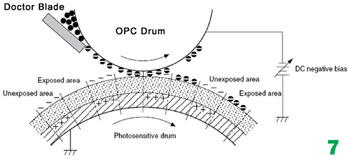
As the laser
exposed areas of the OPC Drum approach the developer roller, the toner
particles are attracted to the drum’s surface due to the opposite
voltage potentials of the toner, and laser exposed areas of the OPC
drum. See Figure 7.
The fourth stage is the transfer stage. This is
where there are some large differences from monochrome printers and also
from other color lasers.
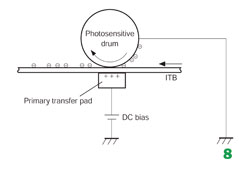
In the Primary transfer stage the
transfer pad (Not a roller in this case) which is located directly
opposite each OPC drum, places a positive DC bias charge on the back of
the ITB or Image Transfer Belt. Each toner cartridge has a separate
transfer charge pad.
The image is transferred from the drum
directly to the ITB. This process is repeated for each color cartridge
in the following order: Yellow, Magenta, Cyan, and Black. At the same
time, the paper is moving between the Secondary transfer roller and the
ITB. As the ITB passes the Secondary transfer roller, the positive
charge is picked up, and draws the negatively charged toner off the Belt
and onto the paper. See Figure 8.
The
paper separates from the ITB belt as the belt reaches the top of its
path and turns back down to start the process again. The static charge
on the back of the paper is decreased with static charge eliminator.
This helps stabilize the paper feed, and also prevents toner flares
(spots) under low temperature and low humidity conditions. See Figure
9.
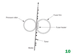
In the fifth stage, the image is then fused
onto the paper by the fuser assembly. The fuser Assembly is comprised of
the upper heating assembly and lower pressure roller. The lower
pressure roller presses the page up into the upper heating assembly
which then melts the toner into the paper. This heating assembly
consists of a flexible sleeve with a ceramic heating coil inside. This
type of fuser affords "instant on” fusing with little to no wait time,
and low power consumption. See Figure 10.
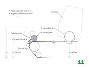
ITB Cleaning
The ITB is
cleaned by both the ITB cleaning Roller, and the ITB Cleaning brush.
Both the roller and brush have a DC positive bias placed on them which
in turn places a positive DC Bias on the residual toner. The Residual
toner is then picked up by the OPC drum (Because of the positive bias)
and then cleaned off the drum by the wiper blade. See Figure 11.
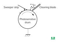
OPC Drum Cleaning
The
drum is cleaned after the image is transferred to the paper by the wiper
blade. This part is fairly standard; the wiper blade scrapes the toner
off the drum, and the recovery blade guides it into the waste chamber. See
Figure 12.
Printer Calibration
At
the start of all this is the cartridge detection process, toner level
detection, and then the calibration cycle. The printer will calibrate
itself whenever the printer is turned on (Within 15 minutes), when a new
toner cartridge is installed and after 48 hours of run time.
Calibration consists of a solid block and halftone of each color being
printed to the ITB. As the printed areas get to the top of the belt, a
sensor will detect them, measure the density, and adjust the printer
accordingly. All of the calibration time settings are user controllable.
Taking
test prints, cartridge troubleshooting as well as minor printer
troubleshooting will be covered at the end of this article.
Remanufacturing
instructions
Required Tools
1) Toner
approved vacuum. 2) A small screw driver (Common Style) 3) A
Phillips head screwdriver 4) Needle Nose Pliers
Supplies
Required
1) CP2025 Dedicated Color Toner 2) New
replacement chip 3) New Long Life CP2025 Drum 4) New Wiper Blade 5)
New toner feed roller [Optional] 6) New PCR [Optional] 7) New
Doctor Blade [Optional] 8) Drum Cover 9) Lint free Cloths 10)
Conductive grease
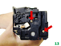
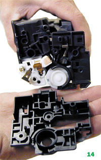
[1] With the label on top and facing you, remove
the two screws from the left side end cap. Remove the end cap. See
Figures 13 and 14.
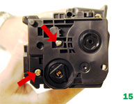
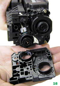
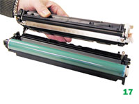
[2] On the right side, remove the two
screws and end cap. Be careful! The two halves will start to separate,
and the drum will come loose! See Figures 15, 16 and 17.
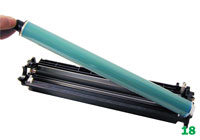
[3] Flip the waste chamber upside down,
and remove the drum. See Figure 18.
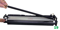
[4] Remove the PCR. Clean with your preferred
PCR cleaner, and place aside. See Figure 19.
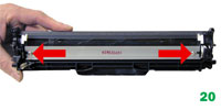
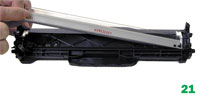
[5] Remove the two screws and wiper blade. See
Figures 20 and 21.
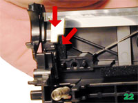
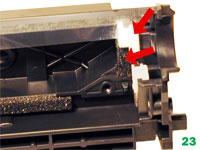
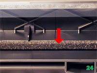
[6] Clean out all the waste toner from the
chamber. Make sure all the wiper blade seals are clean. See Figures
22, 23 and 24.
[7] Coat the new wiper blade with your
preferred lubricant and install. Install the two screws. See Figure
25.
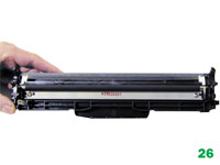
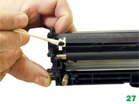
[8] Install the cleaned PCR. Make sure to
place a small amount of conductive grease on the black PCR holder. See
Figures 26 and 27.
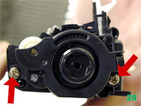
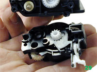
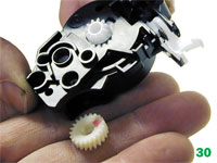
[9] On the Supply chamber, remove the two
screws from the gear side end cap. Lift up on the tab as shown and
carefully work the end cap off the hopper. The end cap contains a set of
gears, and the drive gear for the developer roller will come loose. Be
careful not to lose the gear! Also on this end cap is a spring loaded
arm assembly. This arm we believe locks the cartridge in place once the
tray is inserted and the cover closed. See Figures 28, 29 and 30.
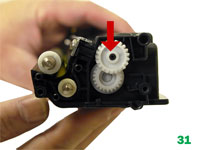
[10] Remove the idle gear as shown. Leave the
other gear in place as it will not come off, and is very difficult to
match back up with the toner auger shaft inside the hopper. See
Figure 31.
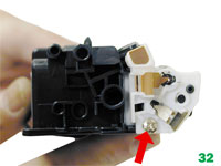
[11] Remove the screw on the contact side end
cap. Remove the end cap. See Figure 32.
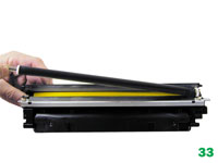
[12] Slide the developer roller over and
remove. See Figure 33.
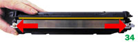
[13] Remove the two screws and doctor blade. See
Figure 34.
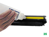
[14] At this point, while tight, you can clean
and fill the hopper with 2025 toner. See Figure 35.
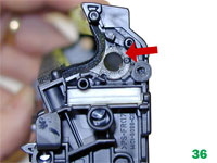
NOTE: HP/Canon created a bit of a block for us
here. The clear bushing located on the right side of the hopper. (See
Figure 36) is glued in. The opposite side bushing is integral to
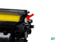
the hopper. If you wish to
install a seal, change the feed roller, or just have better access to
the hopper, the feed roller must be pulled over to one side compressing
the foam. First remove the two white felt seals. See Figure 37.
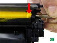
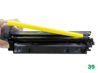
At this point we do not know if this will damage the
roller or affect the printing at all. So far in our tests it has not,
but it’s too early to say for sure. See Figures 38 and 39.
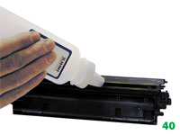
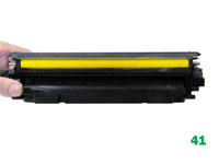
[15] If you have not already done so, fill the
hopper with HP CLJ CP2025 toner and install the feed roller. See
Figure 40 and 41.
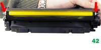
[16] Install the two white felt seals on
the feed roller shaft. See Figure 42.
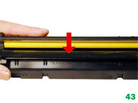
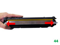
[17] Clean the doctor blade foam seal. Install
the doctor blade and two screws. See Figures 43 and 44.
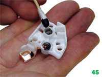
[18] Clean the contact on the contact end
cap with a cotton swab and alcohol. Replace the conductive grease with
fresh grease. Remember, more is not better with this grease. See
Figure 45.
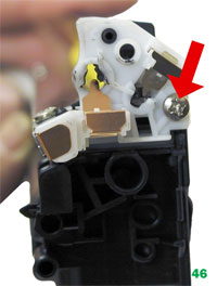
[19] Replace the contact end cap and screw. See
Figure 46.
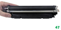
[20] Install the developer roller. See
Figure 47.
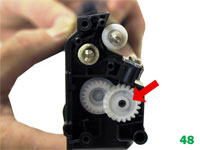
[21] Replace the idle gear as shown. See
Figure 48.
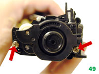
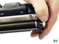
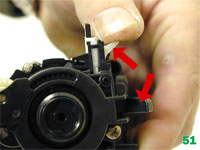
[22] Install the gear end cap and screws. Turn
the developer roller so it mates properly with the drive gear. Make
sure the spring arm works! See Figures 49, 50 and 51.
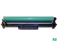
[23] Coat the drum with you preferred
lubricant and install the drum in the waste hopper. See Figure 52.
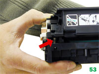
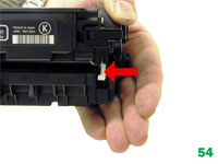
[24] Hold the two halves together. Align the
spring on one side and the spring loaded arm on the other. See
Figures 53 and 54.
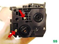
[25] Install the outer gear side and cap
and two screws. See Figure 55.
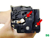
[26] Install the remaining outer end cap on
the contact side of the cartridge and two screws. See Figure 56.
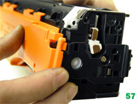
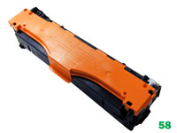
[27] Install the drum cover on to the
cartridge. Spread the two halves apart slightly so it fits properly. See
Figures 57 and 58.
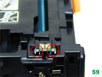
[28] Remove the chip by cutting the
plastic off the edges of both side of the chip. See Figure 59.
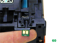
[29] Remove and replace the chip. See
Figure 60.
[30] If the new replacement chip is loose in
the slot. Close off the top edges with small amounts of hot glue.
Taking Test Prints
Press OK to open the menus
Press
the left or right arrow until "REPORTS” appears on the display. Press
OK.
Press the left or right arrow until the report you want is
shown. Press OK.
There are multiple reports to choose from: Demo
page, Menu, Configuration, Supplies status, Font, Color usage, service
and more are available
Most of the error messages are in
plain English, but some are numeric only. We have listed the more common
ones here. Most of the internal errors listed in the service manual
just state something like "Internal hardware error.” They are not very
helpful.
10.000X Supply Error: Chip cannot be read or
cartridge is not properly installed
Internal hardware error. (This can be caused if a surge protector is
being used. HP recommends removing it and plugging directly into the
wall in the case.
Calibrate Now
Sometimes
the only way to fix print quality issues is to force a calibration.
Open
the HP Color LaserJet Toolbox Click the device settings folder, then
click on the Print Quality page In the area for color calibration,
select Calibrate Now. Click Apply to start the process.
Print
Density Settings
These functions are only available
through the Tool Box.
There are actually multiple sub settings
that can be set under density. As you can see, these settings can get a
little intense and complicated.
Contrasts: Contrast is the
range of difference between light (Highlight) and dark (Shadow) colors.
To increase the overall range between light and dark colors, increase
the Contrasts setting.
Highlights: Highlights are colors
that are nearly white. To darken highlight colors, increase the
Highlights setting. This adjustment does not affect midtone or shadow
colors.
Midtones: Midtones are colors that are halfway
between a white and solid density. To darken midtone colors, increase
the midtone setting. This adjustment does not affect highlight or shadow
colors.
Shadows: Shadows are colors that are nearly a
solid density. To darken shadow colors, increase the shadows setting.
This adjustment does not affect highlight or midtone colors.