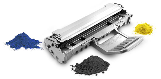
Remanufacturing the Canon Laser Class 810 and 830 Series FX11 Toner Cartridge
First introduced in June 2008, the Laser Class 810 and 830i machines are based on a 23-ppm, 1,200-dpi Canon engine. The cartridge for these machines is the FX11 (1153B001AA) cartridge. The cartridge is rated for 4,500 pages at 5 percent coverage.
The machines based on the MF6500 series engine are the:
Laser Class 810
Laser Class 830i
These machines are multifunction in that they print, fax, copy and scan.
As this is one of the newest Canon cartridges, it is interesting to note that the cartridge does not use a chip, no plastic rivets are used, and the plastic parts of the cartridge are not glued or welded in any way (as with all the newer HP cartridges). As with the HP 1200/1300 and others, two small holes have to be drilled in the top to allow for the axle pin removal.
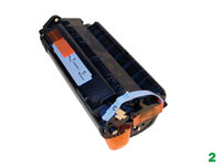
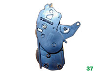
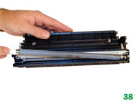
Figures 1 and 2 show a replacement cartridge as received. Note the tape that holds the side handle down and the center handle in place. Be careful not to lose/break the side blue handle. This cartridge sits deep into the machine, and without this handle, removing it will be very difficult.

Remanufacturing instructions
 Cartridge troubleshooting as well as
running test pages, cleaning pages and some simple printer
troubleshooting will be covered at the end of this article.
Cartridge troubleshooting as well as
running test pages, cleaning pages and some simple printer
troubleshooting will be covered at the end of this article.
The pins in these cartridges are very similar to the HP 1200/1300 cartridges. The best way to remove them without damaging the cartridge is to cut two small holes. Other than the location, it is basically the same procedure as the 1200/1300.
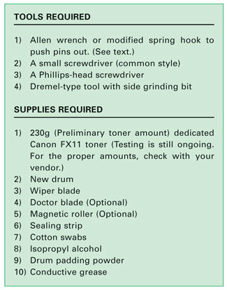
1. Remove the screw and blue side handle (It gets in the way). See Figure 3.

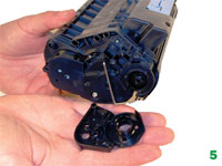
2. With the center blue handle facing you, remove the two screws and drum hub on the left side of the cartridge. See Figures 4 and 5.
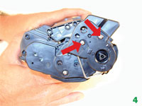
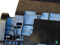
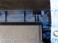
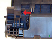
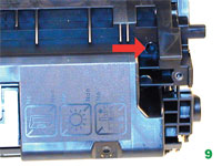
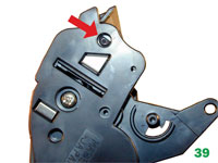
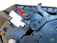
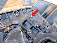
3. Drill a shallow hole on each side of the cartridge as indicated by Figures 6 and 7 (uncut), and 8 and 9 (cut).
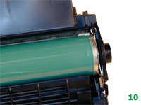
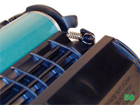
4. Turn the cartridge over so the center blue handle is facing you but also facing down. Note the small spring across the left (non-gear) side of the drum. Remove the spring. See Figure 10.
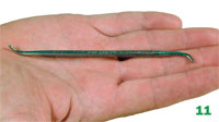
5. Push the pins out with a modified spring hook or a jewelers screwdriver. Remove the pins with a pair of wire cutters. Figure 11 shows a modified spring hook, Figures 12 and 13 show the pins.

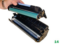
6. Separate the two halves. See Figure 14.
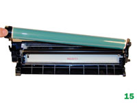
7. On the drum/waste section, remove the drum. See Figure 15.
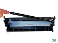
8. Remove the PCR and clean with your standard PCR cleaner. See Figure 16.
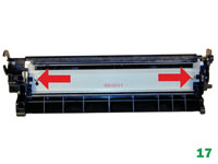
9. Remove the two screws and wiper blade. See Figure 17.
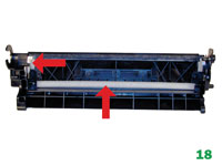
10. Clean out the waste toner. Make sure that the side and rear foam seals are clean. See Figure 18.
11. Coat the wiper blade with your preferred lubricant; install the blade and two screws. See Figure 19.

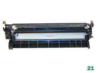
12. Re-install the cleaned PCR. Note that a new OEM PCR has a small amount of conductive grease on the black (contact) side. Clean off the old grease and replace with new. See Figures 20 and 21.
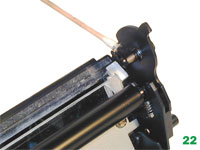
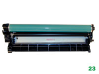
13. Re-install the OPC drum. The metal axle pin should have a good amount of conductive grease on the tip. Remove the old grease and replace before inserting the drum. Place the drum/waste assembly aside. See Figures 22 and 23.
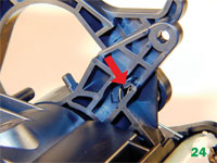
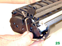
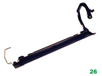
14. On the toner hopper, remove the drum cover. Remove the spring arm by pressing in on the tab located inside the arm pivot point. Pull the metal bar out from the opposite side to remove. See Figures 24, 25 and 26.
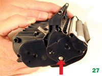
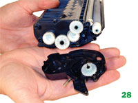
15. On the gear side of the magnetic roller, remove the screw and end cap. See Figures 27 and 28.
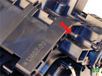
16. Remove the two gears as indicated. The remaining two gears should not be removed. They will not fall off, and are mounted to the toner augers inside the hopper. See Figure 29.

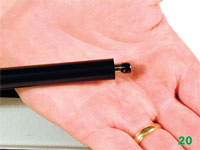
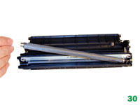
17. Remove the magnetic roller assembly. See Figure 30.
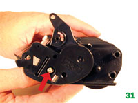
18. On the opposite side of the hopper, remove the screw and end cap. See Figure 31.
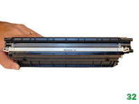
19. Remove the two screws and doctor blade. Pry the blade up from the right side; there is adhesive under the blade and if you pull the blade off the alignment pin may break off. See Figure 32.
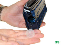
20. Remove the fill plug and dump out any remaining toner. Vacuum/blow the hopper clean. See Figure 33.
21. When a seal becomes available you will install it at this point and fill the hopper through the fill hole. Skip to step 23. See Figure 34.

22. Otherwise, install the fill plug; fill with 230g Canon FX11 toner. (Preliminary weight).
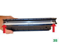
23. Re-install the doctor blade, plastic scrapers and two screws. See Figure 35.
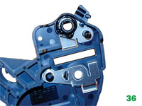
24. On the electrical end cap, clean the old grease off the contact plate and replace with new conductive grease. See Figure 36.
25. Install the electrical end cap and screw. See Figure 37.
26. Install the mag roller assembly. Make sure the keyed end fits properly into the keyed slot in the end cap. See Figure 38 and 39.
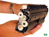
27. On the opposite side of the hopper, install the two gears as shown. See Figure 40.
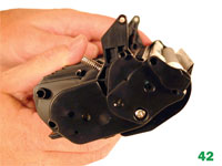
28. Install the gear-side end cap and screw. Make sure the gears mesh properly. See Figures 41 and 42.

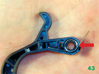
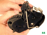
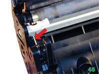
29. Install the drum cover. Place the spring in the arm as shown. Install the arm, place the bar in the hole, and release the arm spring. Rotate the spring a few times to make sure everything is working properly. See Figures 43, 44 and 45.
30. Place the two halves together, make sure the arms on the toner hopper are aligned and insert the two pins. Make sure that the pins are inserted fully so that they do not come loose. See Figures 46 and 47.
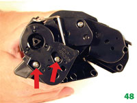
31. Install the drum hub and two screws. See Figure 48.
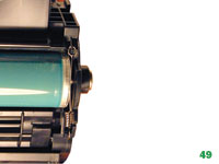
32. Install the small spring across the two small plastic tabs on the non-gear side of the drum. Installing this spring can be a bit tricky. Install the large loop side of the spring on the waste hopper first, and pull it across to the toner hopper with a spring hook. See Figures 49 and 50.
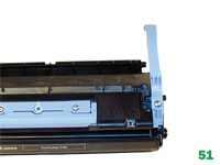
33. Install the blue handle and screw. See Figure 51.
Troubleshooting
Repetitive Defect Chart:
OPC drum: 76mm
Magnetic roller: 38mm
PCR: 36mm
Running Test Pages
There are two different ways to run test pages. The easiest way is to just use the scanner to make copies. The other way is to run them from the printer driver menu.