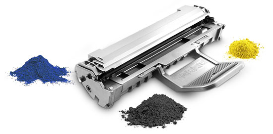
Remanufacturing the HP CP1215
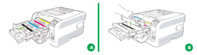
First released in April 2008, the CP1215 series of color laser printers is based on a 12-ppm (black), 8-ppm (color), 600-dpi engine. (2,400 dpi with RET in the CP1215 and up to 3,600 dpi with RET in the CP 1518ni/CM 1312nfi MFP.) The 1215 cartridges are an all-in-one-type cartridge that consists of the toner supply, drum and waste chamber. Like the CLJ-2600 these machines use an in-line, or single-pass system. The difference here is that all four cartridges are stacked in line, front to back, instead of on top of each other as in the 2600. See Figures A and B.
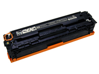
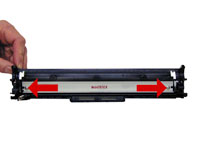
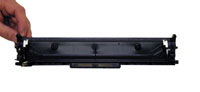
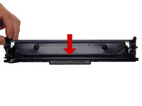
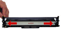
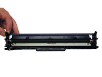
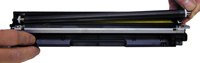
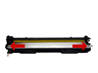
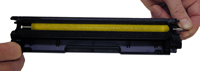
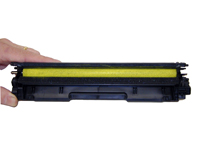
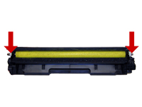
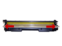
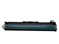
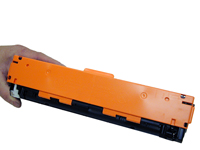
Because of this new machine layout, we will take a moment and run through the printer theory before we get started. The cartridge itself looks different from any previous Canon/HP cartridges I have seen. It’s basically a rectangular-shaped cartridge that comes with a toner seal and a snap-on drum cover across the bottom to protect the drum. See Figures 1 and 1A. New machines ship with starter cartridges rated for 750 pages so users will run out of toner fairly quickly.

These cartridges can be disassembled fairly easily. Unlike the CLJ 2600, no cutting of the drum or cutting of any kind is necessary. There is a small problem removing the feed roller and thus filling the cartridge, but nothing too problematic. That will be explained later in the instructions.
In going through the service manual I found an
intriguing setting. Under the Optimize menu, you can turn on a setting
that reduces
The chips in these cartridges are the same as most other HP color cartridges. The chip does not need to be changed in order for the cartridge to work. The toner-low circuitry will be disabled, but after the user presses the "SELECT” button, the cartridge will work. The display will then alternate from "READY” to "Unauthorized Supply in Use.”
The printers based on the CP1215 engine are the:
HP Color
LaserJet CP1215
HP Color LaserJet CP1515n
HP Color LaserJet
CP1518ni
HP Color LaserJet CM1312nfi MFP
The cartridges used in these machines are the:
CB540A (Black) 2,200 pages
$98.58 List*
CB541A (Cyan) 1,400 pages $91.16 List*
CB543A
(Magenta) 1,400 pages $91.16 List*
CB542A (Yellow)
1,400 pages $91.16 List*
* Pricing current as of May 2008. With the new machines shipping with 750-page black and color starter cartridges, there is sure to be a fast-growing demand for remanufactured cartridges.
HP CP1215/1518 color printing theory
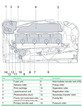
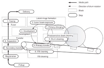
The color toner cartridge printing process happens in a series of stages or steps. For the purpose of this article, we will call them stages. Figure 2 shows the basic layout of the cartridges and how they relate to one another and the printer. Note that while this is still a single-pass system, the layout is completely different from any previous Canon/HP machines. Figure 3 shows the complete image-formation process.
In the first stage, the Primary Charge Roller (PCR) places a uniform negative DC voltage on the OPC drum surface. The amount of the negative DC voltage placed on the drum is controlled by the printer’s intensity setting. See Figure 4.

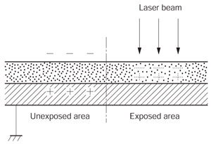
In the second stage, the laser beam is fired onto a rotating mirror (called the scanner). As the mirror rotates, the beam is reflected into a set of focusing lenses. The beam then strikes the drums surface, reducing the negative charge and leaving a latent electrostatic image on the drum. The areas where the laser did not strike the drum will retain the higher negative charge. Technology has advanced tremendously in these machines as there is one laser/scanner unit for all four colors. I imagine there are still four separate lasers, but I’m not sure about the scanner motor(s). The only way to know for sure is to open one up, and I have not done that (yet). See Figures 5 and 6.

The third or developing stage is where the toner is developed on
the drum by the developing section (or supply chamber), which contains
the toner particles. The development stage is actually made up of two
steps: toner charging and the actual development. In the toner-charging
stage, the toner-stirring blade turns inside the hopper.
As it
turns, friction causes a negative potential to develop on the toner. In
addition, a foam feed roller brings the toner to the developer roller
and also places a negative charge on the toner. These two charges help
ensure a uniform charge on the toner. Once the toner is properly
charged, the toner will coat the developer roller. The toner is also
held onto and attracted to the developer roller by another negative DC
bias voltage. This voltage is controlled by the printer’s intensity
setting and causes either more or less toner to be attracted by the
developer roller. This in turn will either increase or decrease the
print density. The amount of toner on the developer roller is controlled
by the doctor blade, which uses pressure to keep the amount of toner on
the roller constant.
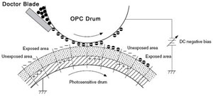
As the laser-exposed areas of the OPC drum approach the developer roller, the toner particles are attracted to the drum’s surface due to the opposite voltage potentials of the toner and laser-exposed areas of the OPC drum. See Figure 7.
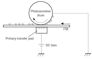
The fourth stage is the transfer stage. This is where there are some large differences from monochrome printers and also from other color lasers. In the primary transfer stage the transfer pad (not a roller in this case), which is located directly opposite each OPC drum, places a positive DC bias charge on the back of the image transfer belt (ITB).
Each toner cartridge has a separate transfer charge pad. The image is transferred from the drum directly to the ITB. This process is repeated for each color cartridge in the order of yellow, magenta, cyan and then black. At the same time, the paper is moving between the secondary transfer roller and the ITB. As the ITB passes the secondary transfer roller, the positive charge is picked up and draws the negatively charged toner off the belt and onto the paper. See Figure 8.
The paper separates from the ITB belt as the belt reaches the top of its path and turns back down to start the process again. The static charge on the back of the paper is decreased with static charge eliminator. This helps stabilize the paper feed and also prevents toner flares (spots) under low-temperature and low-humidity conditions. See Figure 9.

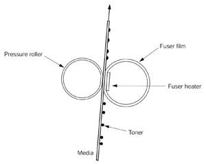
In the fifth stage, the image is then fused onto the paper by the fuser assembly. The fuser assembly is comprised of the upper heating assembly and lower pressure roller. The lower pressure roller presses the page up into the upper heating assembly, which then melts the toner into the paper. This heating assembly consists of a flexible sleeve with a ceramic heating coil inside. This type of fuser affords "instant on” fusing with little to no wait time, and low power consumption. See Figure 10.
ITB cleaning
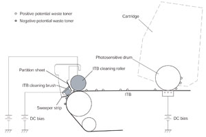
The ITB is cleaned by both the ITB cleaning roller and the ITB cleaning brush. Both the roller and brush have a DC positive bias placed on them, which in turn places a positive DC bias on the residual toner. The residual toner is then picked up by the OPC drum (because of the positive bias) and then cleaned off the drum by the wiper blade. See Figure 11.
OPC drum cleaning
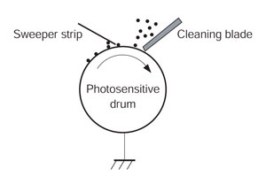
The drum is cleaned after the image is transferred to the paper by the wiper blade. This part is fairly standard. The wiper blade scrapes the toner off the drum and the recovery blade guides it into the waste chamber. See Figure 12.
Printer calibration
At the start of all this is the cartridge detection process, toner-level detection and then the calibration cycle. The printer will calibrate whenever the printer is turned on (within 15 minutes), when a new toner cartridge is installed, and after 48 hours of run time. Calibration consists of a solid block and halftone of each color being printed to the ITB. As the printed areas get to the top of the belt, a sensor will detect them, measure the density, and adjust the printer accordingly. All of the calibration time settings are user-controllable.
Taking test prints, cartridge troubleshooting as well as minor printer troubleshooting will be covered at the end of this article.
Tools required
1)
Toner-approved vacuum
2) A small screwdriver (common
style)
3) A Phillips-head screwdriver
4)
Needle-nose pliers
Supplies required
1)
CP1215 dedicated color toner
2) New replacement chip
3)
New long-life CP1215 drum
4) New wiper blade
5)
New toner feed roller (optional)
6) New PCR (optional)
7)
New doctor blade (optional)
8) Drum cover
9)
Lint-free cloths
10) Conductive grease
Remanufacturing instructions
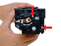
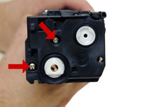
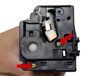
With the label on top and facing you, remove the two screws from the left-side end cap. Remove the end cap. See Figures 13 and 14.

On the right side, remove the two screws and end cap. Be careful! The halves will start to separate and the drum will come loose. See Figures 15, 16 and 17.
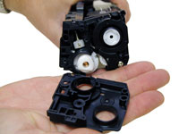

Flip the waste chamber upside down and remove the drum. See Figure 18.

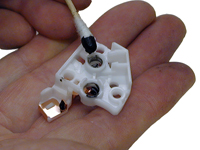
Remove the PCR. Clean with your preferred PCR cleaner and place aside. See Figure 19.

Remove the two screws and wiper blade. See Figures 20 and 21.
Clean out all the waste toner from the chamber. Make sure all the wiper blade seals are clean. See Figures 22, 23 and 24.


Coat the new wiper blade with your preferred lubricant and install. Install the two screws. See Figure 25.
Install the cleaned PCR. Make sure to place a small amount of conductive grease on the black PCR holder. See Figures 26 and 27.
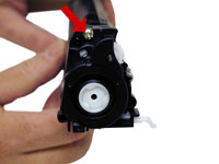
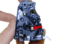
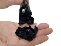
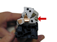
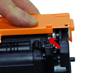
On the supply chamber, remove the screw from the gear/non-contact-side end cap. Carefully and gently work the end cap off the hopper. There is a small plastic pin that will break off. See Figures 28 and 29.

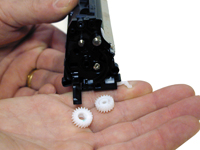
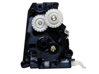
Remove the two gears. See Figure 30.
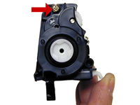
Remove the screw on the contact-side end cap. See Figure 31.
Slide the developer roller over and remove. See Figure 32.
Remove the two screws and doctor blade. See Figure 33.
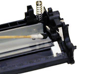
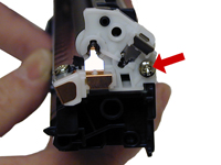
On the gear side of the hopper, remove the screw and inner end cap. Carefully work this end cap free. Use a small screwdriver if necessary to free the end cap from the plastic pin that broke earlier. Note the spring-loaded arm assembly. I believe this arm is part of the cartridge detection system but nothing is mentioned about it in the service manual. The sensors for this are hidden by the transfer belt in the machine. We will eventually figure out their purpose, but for now it’s just a guess. See Figures 34, 35 and 36.

At this point, while tight, you can clean and fill the hopper with 1215 toner. See Figure 37.

NOTE: HP/Canon created a bit of a block for us here. The clear bushing located on the right side of the hopper (see Figure 38) is glued in. The opposite-side bushing is integral to the hopper.

If you wish to install a seal then change the feed roller or just have better access to the hopper. The feed roller must be pulled over to one side compressing the foam. First remove the two white felt seals. See Figure 39.

At this point we do not know if this will damage the roller or affect the printing at all. So far in our tests it has not, but it’s too early to say for sure. See Figures 40 and 41.

If you have not already done so, fill the hopper with HP CLJ CP1215 toner and install the feed roller. See Figures 42 and 43.

Install the two white felt seals on the feed roller shaft. See Figure 44.
Clean the doctor blade foam seal. Install the doctor blade and two screws. See Figures 45 and 46.

Install the developer roller. See Figure 47.

Install the inner end cap and screw. This end cap has a tight fit and snaps in place. Be careful here, the screw hole strips out easily. See Figure 48.

Clean the contact on the contact end cap with a cotton swab and alcohol. Replace the conductive grease with fresh grease. Remember, more is not better with this grease. See Figure 49.
Replace the contact end cap and screw. See Figure 50.
Replace the two gears on the feed and developer roller shafts. See Figure 51.
Install the gear end cap and screw. Make sure the spring arm works. See Figures 52 and 53.

Coat the drum with you preferred lubricant and install the drum in the waste hopper. See Figure 54.
Hold the halves together. Align the spring on one side and the spring-loaded arm on the other. See Figures 55 and 56.


Install the outer gear side and cap, and two screws. See Figure 57.

Install the remaining outer end cap on the contact side of the cartridge and two screws. See Figure 58.
Install the drum cover onto the cartridge. Spread the halves apart slightly so it fits properly. See Figures 59 and 60.
Remove the chip by cutting the plastic off the edges of both sides of the chip. See Figure 61.

Remove and replace the chip. See Figure 62.

If the new replacement chip is loose in the slot then close off the top edges with small amounts of hot glue.
TAKING TEST PRINTS
Demo Page CP-1210
The demo page for this machine can only be run from the toolbox provided with the software driver.
Demo Page CP-1518
Press OK to
open the menus
Press the left or right arrow until "REPORTS” appears
on the display. Press OK
Press the left or right arrow until "DEMO
PAGE” appears on the display. Press OK
Press X to exit the menus
Configuration Page CP-1210
Press and hold the RESUME button for three
seconds. Both the Configuration page and a Supplies Status page will
print out.
Configuration Page CP-1518
Press OK to open the menus
Press
the left or right arrow until "REPORTS” appears on the display. Press
OK
Press the left or right arrow until "CONFIG REPORT” appears on the
display. Press OK
Press X to exit the menus
Engine test page
With the printer turned off, open the front and rear
doors
Turn the power on, and close both doors within 10 seconds.
An
Engine test page will print containing multiple horizontal colored
lines
REPETITIVE DEFECT CHART
ITB
633.6mm (distance is longer than one full page!)
OPC Drum — 75.8mm
Transfer
Rollers — 57.0mm
Fuser Pressure Roller — 56.8mm
Fuser Sleeve —
56.5mm
Registration Roller — 44.0mm
RS Roller (Feed roller) —
28.5mm
Primary Charge Roller — 26.7mm
Developer Roller Sleeve —
22.3mm
COMMON PRINTER ERROR MESSAGES
CP-1210
These machines have simple lights that show if a specific cartridge is low or out of toner, paper jam, etc. More detailed messages are displayed on the PC it is attached to.
CP-1518
Most of the error messages are in plain English, but some are numeric only. We have listed the more common ones here. Most of the internal errors listed in the service manual just state something like "Internal hardware error.” They are not very helpful.
10.000X Supply Error: Chip cannot be read
or cartridge is not properly installed
10.0000 Black chip error
10.0001
Cyan chip error
10.0002 Magenta chip error
10.0003
Yellow chip error
10.100X Supply Error: Cartridge/chip is missing
10.1000
Black cartridge/chip missing
10.1001 Cyan cartridge/chip
missing
10.1002 Magenta cartridge/chip missing
10.1003
Yellow cartridge/chip missing
51.XX Printer Error
Internal hardware error. (That’s all the service manual states!)
Calibrate now
Sometimes the only way to fix print-quality issues
is to force a calibration.
Open the HP Color LaserJet toolbox
Click
the device settings folder, then click on the Print Quality page
In
the area for color calibration, select Calibrate Now
Click Apply to
start the process
CARTRIDGE-LIFE SETTINGartridge-life settings
Lastly there are some interesting settings the user can set for cartridge life. On the CP1518 machines, open up the System Setup menu/Print Quality/Cartridge Low or Replace Supplies menu through the control panel. For the CP1215 machine these functions are only available through the Tool Box.
For toner low, you can set the percentage that the printer starts reporting low toner. This can be set from 1 to 20 percent. The default setting is 10 percent.
Replace supplies: This setting can be turned on or off. If the "Override Out” setting is chosen, you can continue printing until the toner is depleted. The other setting is "Stop At Out.” This setting stops all printing until the cartridge is replaced. This is the default setting.
PRINT-DENSITY SETTINGS
On the CP1518 machines, open up the System Setup menu/Print Quality/Print Density menu through the control panel. For the CP1215 machine these functions are only available through the Tool Box.
There are actually multiple sub-settings that can be set under Density. As you can see, these settings can get a little intense and complicated.
Contrast is the range of difference between light (highlight) and dark (shadow) colors. To increase the overall range between light and dark colors, increase the Contrast setting.
Highlights are colors that are nearly white. To darken highlight colors, increase the Highlight setting. This adjustment does not affect midtone or shadow colors.
Midtones are colors that are halfway between a white and solid density. To darken midtone colors, increase the Midtone setting. This adjustment does not affect highlight or shadow colors.
Shadows are colors that are nearly a solid density. To darken shadow colors, increase the Shadows setting. This adjustment does not affect highlight or midtone colors.
Mike Josiah is technical director at Summit Technologies, a division of UniNet Imaging Inc., a global distributor of toner, OPC drums, wiper blades and other supplies. Josiah has been with the company since 1987. He and his technical support team regularly contribute articles and teach seminars at association meetings and trade shows. Contact him at 631-218-8376 or mjosiah@uninetimaging.com.
About the Author
Mike Josiah is the East Coast technical director at
Uninet East Coast, a global distributor of toner, OPC drums, wiper
blades and other supplies. He and his support team contribute articles
and teach seminars at association meetings and trade shows.