Remanufacturing, Refill the HP LaserJet P2035/2055
Remanufacturing the HP LaserJet
P2035/2055
By Mike Josiah
Mar 01, 2009
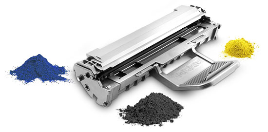
First introduced in November 2008,
the HP-P2035/2055 series of laser printers is based on a 30-35 ppm,
1,200 dpi Canon engine that comes standard with 16 MB memory in the 2030
and 64 MB in the 2050 series.
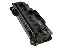
Two different cartridges are
available for this series: the CE505A (rated at 2,300 pages) and the
CE505X (rated for 6,500 pages).
For the P2030 series, only the
CE505A cartridge will fit. Figures 1 and 2 show the different
sizes of the cartridges.
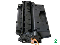
The cartridges are similar
in design to the 1160/1320 cartridges, but are not interchangeable. The
drum drive gear is a completely new system. See Figure 3.
The actual drive gear
is a floating type that uses a ball-and-socket configuration.
There
are also no screws used to hold the cartridge together. All the end
caps and bushings are held in place by plastic welds. This sounds worse
than it is though; it's a little harder to take apart than a 1320, but
not that bad.
The pin system holding the two halves of the
cartridge together is similar to the HP-1160/1320. You will need two
small holes cut in the top to get access to the pins. The pin access
hole location on these cartridges is almost identical and the same
methods you use for the 1320 should work here.
The printers
released in this series so far are:
P2035, P2035n, P2055d,
P2055dn, P2055x
Cartridge troubleshooting, as well as running test
pages, cleaning pages and some simple printer troubleshooting will be
covered at the end of this article.
Remanufacturing
instructions
The pins in these cartridges are very similar
to the HP-1160/1320 cartridges. The best way to remove them without
damaging the cartridge is to cut two small holes. Other than the
location, basically the same procedure as the 1160/1320 is used.
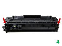
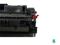
[1]
Remove the drum cover by prying up on each end. Note the spring
position so that it can be replaced later. See Figures 4 and 5.
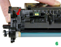
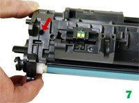
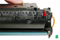
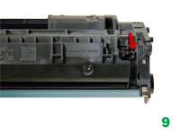
[2] Drill a shallow hole on
each side of the cartridge as indicated by Figures 6, 7 (uncut), 8,
and 9 (cut).
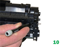
[3] Push the pins out with a
jewelers screwdriver. Push the jewelers screwdriver through the hole and
the pins will be pushed out. Remove the pins. See Figure 10.
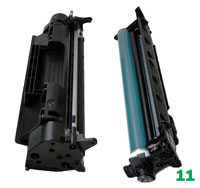
[4 Separate the two halves. See
Figure 11.
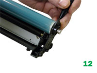
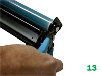
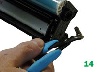
[5] With a flathead screwdriver,
press the drum axle pin out from the inside of the cartridge wall as
shown. There is a small shoulder visible that the screwdriver should be
pressed against. Make sure not to bend or damage the plastic wall — the
plastic is thin and easily damaged. Remove the axle pin from the outside
with flush-cutting wire cutters. See Figures 12, 13 and 14.
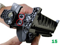
Note: The drum hub on the opposite side
is welded. The weld can be broken or drilled out, but there is a good
chance that the hub will either warp if pried off, or will be hard to
align if drilled out. See Figure 15.
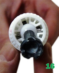
[6] Remove the drum. See Figure 16.
This is a good time to look at the new drive gear(s). This is a
completely new system. New drums and gears are being developed.
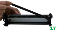
[7] Remove the PCR and clean with standard PCR
cleaner. See Figure 17.
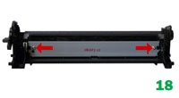
[8] Remove the two screws and wiper
blade. See Figure 18. Clean out the waste toner.
[9] Coat the wiper blade with your
preferred lubricant. Install the blade and two screws. See Figure 19.
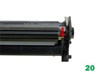
[10] Re-install the cleaned
PCR. Note that a new OEM PCR has a small amount of conductive grease on
the black (contact) side. See Figure 20.
[11] Re-install the OPC drum and
metal axle pin. The metal axle pin should have a small amount of
conductive grease on the tip. Remove the old grease and replace before
inserting the pin. Make sure the axle pin is fully inserted. See
Figures 21 and 22.
[12] Slice the two tabs off each
location as shown on the left (seal) end cap. Use a square blade X-Acto
knife to slice off the tabs. See Figure 23.
NOTE: Both the
end caps are plastic welded in place. The only way to open them up is
to cut the welds and carefully drill them out. We have found the left
(non-gear) side is the best side to do this on.
[13] Using the
3/32-inch drill bit, drill out each of the two welds. Be careful to keep
the drill straight as you drill in. Use a slow speed and drill in no
more than a quarter inch. See Figure 24.
[14] With a
flathead screwdriver, work the edge of the blade around the edge of the
end cap and gently pry up the end cap. You will hear the remaining parts
of the welds break free. The top weld will also break off now. [15]
Take your time with this. See Figure 25.
[16] Remove the
magnetic roller assembly. See Figure 26.
[17] Remove
the magnetic roller drive gear. The end cap will keep the bushing in
place. See Figure 27.
[18] Remove the doctor blade and two
screws.See Figure 28.
[19] Clean out any remaining toner
from the hopper. Note the doctor blade seal. It is a sticky substance
that can be cleaned with alcohol if toner gets on it. See Figure 29.
[20] Fill through the mag roller opening with 110 grams of P2035
toner for the "A” cartridge, 290 grams for the "X.” There is not a fill
plug in these cartridges. See Figure 30.
[21] If you are
going to seal the cartridge, there is a white plastic shelf that needs
to be removed. See Figure 31. The shelf is held on with double-sided
tape. It can be gently pried off with a small screwdriver.
[22]
Re-install the white plastic shelf. If the adhesive is not working,
replace it with a good double-sided tape. This shelf helps with the flow
of toner in the hopper. See Figure 32.
[23] Re-install the
doctor blade and two screws. See Figure 33.
[24] Clean the
old grease off the contact plate, and replace with new conductive
grease. See Figure 34.
[25] Re-assemble the toner
hopper section. Place the mag roller drive gear in place, install the
magnetic roller assembly. Turn the roller until the keyed end fits into
the drive gear properly. Install the end cap, align the keyed magnet
into the keyed slot on the gear side first. This will help in aligning
the opposite end cap. See Figures 35, 36 and 37.
[26]
Install two small screws into the holes previously drilled out. Leave
the top third hole alone. (This weld was broken when the end cap was
removed). A screw here will interfere with installing the cartridge in
the printer. In our tests, the two screws will hold the end cap on with
no problems. See Figure 38.
[27] Place the two halves
together, make sure that the two springs are aligned, and insert the two
pins. Make sure that the pins are slightly pushed in so that they do
not interfere with installing the cartridge in the printer. See
Figures 39 and 40.
[28] Install the drum cover;
make sure the spring is situated correctly. See Figures 41 and 42.
[29]
Replace the chip. See Figure 43.
Troubleshooting
Repetitive
Defect Chart:
OPC drum — 75mm Lower fuser roller — 63mm Upper
fuser film — 57mm Registration roller — 43mm Magnetic
roller — 42mm Transfer rolle — 39mm PCR — 38mm
Running
Test Pages
P2030 series only
To run the demo
page, make sure that the ready light is on, and briefly press the go
button. The demo page will print.
This can also be run from the
printer driver menu through the PC.
P2050 series only
Press
the OK button.
Press the down arrow to select reports.
Press
the down arrow to select the report wanted, press OK.
The reports
available are:
Demo, menu, config., supplies status, network,
usage, various font pages and a service page, which is a service report.
Running
the Cleaning Page
P2030 only
To run the cleaning
page, make sure that the ready light is on. Insert a transparency in the
paper tray. Open the printer-driver properties screen and click on the
device settings tab.
In the cleaning page area press start.
P2050
only
Insert a transparency in the paper tray. Open HP toolbox
FX and click on the device settings folder.
Click on the
troubleshooting page.
In the cleaning mode area click start.
The
cleaning process takes about two minutes. The cleaning page will stop
periodically during the cleaning process. Do not turn the printer off
until the process has finished. For these printers, HP recommends that
transparencies be used instead of paper.
Printer
Troubleshooting
P2030 series
As with most of
the new low-cost HP machines, these printers do not have a display
panel. All the error codes consist of different pattern of the five
lights, including:
Attention light blinking: Print cartridge door
open.
Bottom three lights on: Fatal error; turn the printer off,
and unplug it for five minutes. If the error still exists, the printer
has a major problem. There is no information yet on what these problems
may be. The service manual simply states to contact HP.
Toner
light blinking: Toner cartridge missing.
Toner light on
steady: Toner low.
Status Alert Messages
P2030
Series
10.X Supply memory error 13.XX Paper jam 50.X
Fuser error 52.0 Scanner error P2050 Series 10.X
Supply memory error 13.XX Paper jam 21.X Print failure 41.2
Engine error 50.X Fuser error 51.X Scanner error 57
Fan error 59.X Main motor error
About
the Author
Mike Josiah is the East Coast technical director at
Uninet East Coast, a global distributor of toner, OPC drums, wiper
blades and other supplies. He and his support team contribute articles
and teach seminars at association meetings and trade shows.
 First introduced in November 2008,
the HP-P2035/2055 series of laser printers is based on a 30-35 ppm,
1,200 dpi Canon engine that comes standard with 16 MB memory in the 2030
and 64 MB in the 2050 series.
First introduced in November 2008,
the HP-P2035/2055 series of laser printers is based on a 30-35 ppm,
1,200 dpi Canon engine that comes standard with 16 MB memory in the 2030
and 64 MB in the 2050 series.
 The actual drive gear
is a floating type that uses a ball-and-socket configuration.
The actual drive gear
is a floating type that uses a ball-and-socket configuration.