Remanufacturing the HP LaserJet P4014, P4015 and P4045 Toner Cartridges
 First introduced in April 2008,
the HP LaserJet P4014 engine is a 45-62 ppm (depending on the model),
1200 dpi engine. These printers will most likely replace the 4200/4300
series.
First introduced in April 2008,
the HP LaserJet P4014 engine is a 45-62 ppm (depending on the model),
1200 dpi engine. These printers will most likely replace the 4200/4300
series.
All of the machines in all three series have a first page out in less than 8.5 seconds, come with 128Mb of ram (Expandable to 640Mb),and have a 400MHz processor. All also come standard with a 10,000 page low yield cartridge. The new CC364A and CC364X cartridges are rated for 10,000 and 24,000 pages respectively. The HY cartridges will not physically fit into the P4014 machines, only in the P4015 and P4515 series.
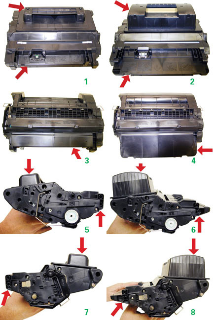
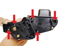
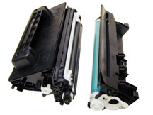
The following Figures (1-8) show the difference between the two cartridges.
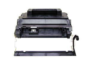
Fig. 1 & 2 Top of 64A, 64X
Fig. 3 & 4 Bottom of 64A, 64X
Fig. 5 & 6 Right side 64A, 64X
Fig. 7 & 8 Left side 64A, 64X
The current machines that use these new cartridges are as follows:
HP LaserJet P4014
HP LaserJet P4014n
HP LaserJet P4015n
HP LaserJet P4015tn
HP LaserJet P4015x
HP LaserJet P4515n
HP LaserJet P4515tn
HP LaserJet P4515x
HP LaserJet P4515xm
Printer usage, as well as some common printer/cartridge problems will be covered at the end of this article.
As these machines use new technology such as dual laser beams, we will run through the theory and explain how the new technology works.
Cartridge Theory
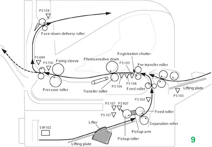
Figure 9 gives a nice view of the cartridge as it relates to the printer.
The image formation process consists of 8 steps which are split up into five functional blocks. See Figure 10 (Step #8, Figure 19 is where the new second laser beam comes in).
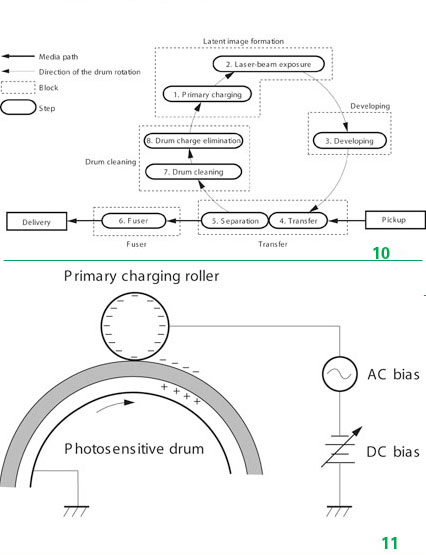
In the first step, the Primary Charge roller (PCR) places a uniform negative DC Bias voltage on the OPC drum surface. The amount of the negative DC Bias placed on the drum is controlled by the printer's intensity setting. This process is part of the latent Image formation block. See Figure 11
In the second step, (also part of the latent Image formation block), the laser beam is fired onto a rotating mirror (called the scanner). As the mirror rotates, the beam reflects into a set of focusing lens. The beam then strikes the OPC's surface, which neutralizes the negative charge on the drum and leaves a latent electrostatic image on the drum. The laser unit actually fires 2 beams. The service manual talks about the second bean being used to erase residual charges, but not if it also helps to write the image. See Figures 12 and 13.

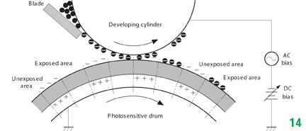
The third step (developing block) is where the toner image is developed on the drum by the developing section, (or supply chamber), which contains the toner particles. The toner is held to the magnetic roller sleeve by the stationary magnet inside the sleeve, and a DC bias voltage supplied by the high voltage power supply. This DC bias voltage is controlled by the printer's density setting, and causes either more or less toner to be attracted to the drum. This in turn will either increase or decrease the print density. Both the Primary Charge roller and magnetic roller DC Bias voltages are controlled by the printer's density setting. The amount of toner on the magnetic roller sleeve is also controlled by the rubber Doctor blade, which uses pressure to keep the amount of toner on the magnetic roller sleeve constant. This blade also causes a static charge to build up on the toner, which helps keep the coating of toner even, and allows easy transfer to the OPC drum.
At the same time an AC signal is also placed on the magnetic roller sleeve. This signal decreases the attraction of the toner to the Magnetic Roller sleeve, and increases the repelling action of toner against the areas of the drum that was not exposed to the laser beam. This AC potential improves the density, and contrast of the toner on the printed page. See Figure 14.
As the laser exposed areas of the OPC drum approach the magnetic roller, the toner particles are attracted to the drums surface due to the opposite voltage potentials of the toner, and laser exposed surface of the OPC drum.
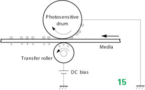 In the fourth step (transfer block) the toner image is
then transferred to the paper as it passes below the drum by the
transfer charge roller, which places a positive charge on the back of
the paper. This positive charge causes the negatively charged toner on
the drum's surface to be attracted to the page. The small diameter of
the drum, combined with the stiffness of the paper causes the paper to
peel away from the drum. See Figure 15.
In the fourth step (transfer block) the toner image is
then transferred to the paper as it passes below the drum by the
transfer charge roller, which places a positive charge on the back of
the paper. This positive charge causes the negatively charged toner on
the drum's surface to be attracted to the page. The small diameter of
the drum, combined with the stiffness of the paper causes the paper to
peel away from the drum. See Figure 15.
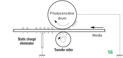
In the fifth step (also part of the transfer block) the paper separates from the drum. The static charge eliminator weakens the attractive forces between the negatively charged drum surface, and the positively charged paper. This prevents toner dropouts onto the paper at low temperatures and humidity and also prevents paper from wrapping around the drum. See Figure 16.
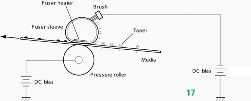
In the Sixth step (fusing block) the image is then fused on to the paper by the fuser assembly, which is comprised of the upper fixing film assembly and the lower fuser roller. The paper passes between a heated upper fixing film assembly and a soft lower rubber roller. The upper heated element then melts the toner into the paper. The fixing film assembly consists of a Teflon sleeve with a ceramic heating element inside. These fusers are a bit different in that they have a Brush which has a DC Bias charge on it to help keep the film clean. See Figure 17.
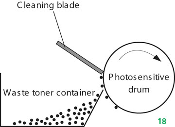
In the Seventh step (Drum cleaning block) the OPC drum is cleaned. On average, approximately 95% of the toner is transferred to the paper during the print cycle. As the drum rotates during printing, the remaining 5% of the toner that is on the OPC drum is cleaned off the drum by the wiper blade. It is then guided into the waste chamber by the recovery blade, and stored in the waste chamber. See Figure 18.
Step 8 is where the residual charge is
eliminated. Here is where there is a major difference 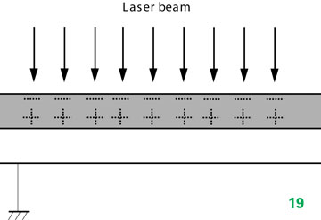 from previous HP
cartridges/printers. In all previous PCR based cartridges, the Primary
Charge Roller places an AC voltage across the drum surface that erases
any residual charges left on the drum surface.
from previous HP
cartridges/printers. In all previous PCR based cartridges, the Primary
Charge Roller places an AC voltage across the drum surface that erases
any residual charges left on the drum surface.
These machines use the new second laser beam to eliminate the residual charges. This drum charge elimination is only turned on during the last rotation period of the drum.
With the higher speeds of these new machines, my guess is that using the PCR to erase the residual charges was not efficient at these speeds. This new laser process is. See Figure 19
1) Toner approved vacuum.
2) A small Common screwdriver
3) A Phillips head screwdriver
4) Needle Nose Pliers
Supplies Needed
Dedicated
P4015 series toner; 465g for the 64A, and 1065g for the 64X
**
Preliminary weights**
Replacement drum
Wiper Blade
Doctor Blade
PCR
Magnetic roller sleeve
Conductive Grease
Hot Glue gun (See text)
1) Place the cartridge with the toner hopper facing up and towards you. This will orient the cartridge for right and left sides.
2) Open the drum cover towards the back of the cartridge. Remove the right side metal bar. See Figure 20.

3) On the opposite side of the cartridge, carefully pry off the drum cover plastic arm. The spring will probably pop off, take care not to loose it. We will go over the installation at the end of this article. Remove the drum cover assembly. See Figure 21

4) Remove the metal bar from the left side, and remove the entire drum cover assembly. Make sure you put the spring in a safe place. See Figure 22
5) Remove the five screws on the right side end cap. See Figure 23
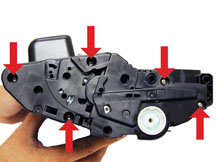
6) Remove the five screws from the left end cap. See Figures 24
7) Remove the right and left side end caps from the cartridge. Note that the gears do not come off the gear (right) end cap. See Figure 25.
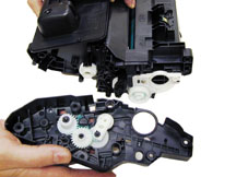
8) Separate the toner hopper and waste chamber. See Figure 26.
9) On the large gear side of the waste chamber, remove the screw and white plastic drum bushing. See Figure 27.
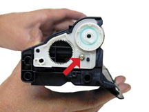
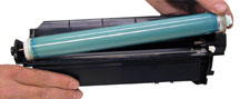
10) Remove the drum. See Figure 28.
11) Remove the PCR. See Figure 29.

12) Remove the two screws from the wiper blade. See Figure 30.

13) Remove the wiper blade from the cartridge, and clean out the waste toner. See Figure 31.

14) Due to the high speed and page counts of these cartridges, we recommend that the wiper blades be replaced. Make sure that the wiper blade foam seals are clean. See Figure 32.

15) Install the new wiper blade and two screws. See Figure 33
16) Clean the PCR with your standard PCR cleaner.
17) Install the cleaned PCR. Place a small amount of conductive grease on the black PCR saddle. Remember, when using conductive grease, more is not better! See Figure 34.

18) On the drum axle pin, clean off the old conductive grease and replace with new. See Figure 35.

19) Install the drum small gear side first onto the drum axle pin. See Figure 36.

20) Install the white plastic drum bushing and screw. If the OEM drum grease is dirty, clean it off with alcohol, and replace with white lithium grease. See Figure 37.

21) On the supply chamber, carefully pry off the Magnetic roller (MRS) cover, and remove. See Figure 38.

22) Remove the MRS drive gear. See Figure 39.

23) Note the location of the spring that sits between the MRS holder and the hopper. Remove the two screws, spring and the holder. See Figures 40 & 41.

24) Remove the MRS assembly. See Figure 42.

25) Remove the two doctor Blade screws and the doctor blade. Note the clear plastic strip that covers the doctor blade screws. Slide the screwdriver under the strip. Be careful not to damage the strip! See Figures 43 & 44.

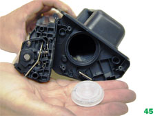
26) Remove the fill plug and clean out all the remaining toner in the supply hopper. See Figure 45.
27) Note the magnetic seals on the MRS and the DB sealing foam. Make sure both are clean. See Figure 46.

28) Note also the new heavy duty style magnetic roller contact. This when combined with the new larger diameter of the roller, allow the cartridge to run at the higher speeds that these machines are capable of. See Figure 47.

29) There are HP-4000 style magnetic roller bushings on each side of the roller. While these are holding up well in our initial tests, this may be an area where wear will cause banding. One will stay in the hopper, and one comes off with the mag. Roller assembly. See Figures 48 & 49.

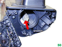
30) Unlike the HP-4300 series where there are three separate mixing blades in the toner hopper. These cartridges just use one large mixing blade inside the toner hopper. See Figure 50.
31) The upper mag. roller section of the toner hopper is different in that is "Floats" on a series of foam seals. The upper half can be removed from the hopper, but some of the seals will be destroyed. This may become necessary in order to seal the cartridge we will keep you informed as our testing continues. The foam isolates the mag roller from the vibrations of the mixing augers, and allows smoother prints.
32) Install the doctor blade and two screws (Make sure that the clear strips are not damaged!) See Figure 51.

33) Install the MRS assembly. Make sure the clear strips from the DB ride on top of the magnetic roller. See Figures 52 & 53.

34) Remove the right side small bushing from the magnetic roller sleeve and install it onto the holder. Make sure the tab on the bushing aligns with the slot in the holder. See Figure 54.

35) Install the holder 2 screws and spring. Make sure the screw holes line up, and that the two locking tabs on the bottom of the holder are in the correct place. See Figures 55 & 56.

36) Install the MRS drive gear. See Figure 57.

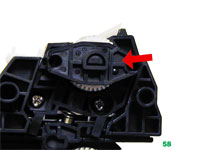
37) Install the keyed MRS cover. Make sure that the keyed hole in the cover matches the keyed end of the magnet in the MRS assembly. See Figure 58.
38) Fill with appropriate amount of P4015 toner, install the fill plug. See Figure 59.

39) Hold the two sections of the cartridge together, and install the left (Contact side) end cap. Install a screw in the waste and supply sections to hold everything together. See Figure 60.

40) Install the right side end cap and five screws. See Figure 61.

41) Install the remaining three screws on the left end cap. See Figure 62.

42) Install the spring into the drum cover arm as shown. Pull the upper tail of the spring until it fits into the notch in the arm hub. See Figure 63.

43) Install the metal bars from the drum cover on both sides of the cartridge. See Figure 64.

44) Install the arm onto the cartridge. Pull the arm fully back to release the spring from the notch. Check to make sure the drum cover operates properly. See Figure 65.

45) Remove the old chip from the top of the cartridge by slicing the melted plastic off with a sharp Xacto knife. Replace the chip; lock the chip in place with a small dab of glue from a hot glue gun. Replacing this chip will enable the toner low functions of both the cartridge, and the machine again. See Figure 66.

Repetitive defect chart:
OPC Drum: 94mm
Upper fuser Sleeve 94mm
Lower fuser pressure Roller 94mm
Tray 2 Separation Roller 79mm
Tray 2 Pickup roller 79mm
Tray 2 Feed Roller 79mm
Tray 1 Separation Roller 79mm
Tray 1 Feed Roller 79mm
Tray 1 Pickup roller 63mm
Magnetic roller 63mm
Transfer Roller 47mm
PCR 37.7mm
Running the Cleaning Page
Press "MENU" on the control panel
Press the down arrow until "CONFIGURE DEVICE" shows on the display
Press the down arrow until "PRINT QUALITY" shows on the display
Press the down arrow until "CREATE CLEANING PAGE" shows on the display
Press OK
Remove all the paper from tray 1
Remove the cleaning page from the output bin and load it face down in tray 1
Press the down arrow until "PROCESS CLEANING PAGE" appears on the display.
Press OK
Running Test Pages
Press "MENU" on the control panel
Press the down arrow until "INFORMATION" shows on the display
Press the down arrow until either:
PRINT MENU MAP,
PRINT CONFIGURATION
PRINT SUPPLIES STATUS PAGE,
PRINT USAGE PAGE
PRINT PCL FONT LIST or
PRINT PS FONT LIST appears on the display
Choose the page(s) desired
Printer error Codes
Most of the error codes are self explanatory but there are a few that are part text, and part number. It is those codes that we will list here.
10.10.00 Supply Memory Error: Bad chip
10. XX.YY Supply Memory Error: An error has occurred in one or more of the printers supplies.
XXOO = Memory is defective
XX01 = Memory is missing
YY00= bad cartridge
Error 10.94.YY remove the shipping locks from the cartridge. Remove the shipping lock(s).
Error 41.X: This code is a Temporary Printer error.
Error 50.X: This code is a Fuser error.
50.1 Low Fuser Temperature
50.2 Fuser warm up slow
50.3 High Fuser Temperature
50.4 Faulty Fuser
Error 51.X: This code is a laser/scanner error
Error 53.XY.ZZ: This code is a Printer Memory error.
Error 54.XX: This code is a typically a sensor issue.