Remanufacturing, Refill the Xerox Phaser 3635MFP Toner Cartridge
Remanufacturing the Xerox
Phaser 3635MFP Toner Cartridge
Nov 01, 2008
First released in August 2008, the
Xerox Phaser 3635MFP printers are based on a 35ppm, 1200dpi engine. The
first page out is rated at under nine seconds, and the monthly duty
cycle is up to 75,000 pages. Both model printers are print, copy, scan,
fax, and e-mail capable.
These cartridges do not have a drum
cover, and come new with a piece of heavy paper with foam glued to it
taped around the cartridge.
There are both LY (5,000 pages) and
HY (10,000 pages) cartridges available. Each version of cartridge has
its own specific chip, but the cartridges themselves are identical.
Methods to reset the OEM chips and/or new replacement chips should be
available as you read this.
The chip covers are held in
place by plastic rivets. To replace the chip, the rivets need to be cut
off, holes carefully drilled, (not too deep or the cartridge will leak),
and screws installed. This is definitely a cartridge where a reset box
is the way to go.
The printers are Xerox Phaser 3635MFP/S and
Xerox Phaser 3635MFP/X. The cartridges are LY cartridge 108R00793 (5,000
pages) and HY cartridge 108R00795 (10,000 pages).
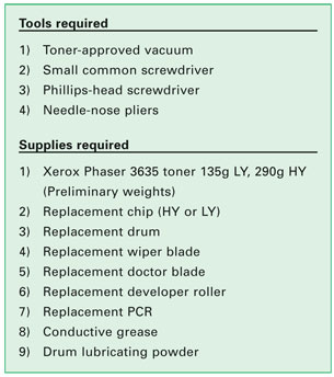
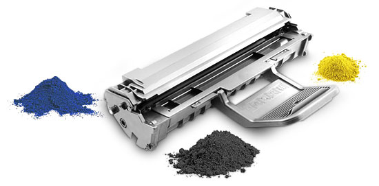
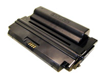
Figure 1
shows the HY and LY cartridges, as you can see, they are identical so
if you install the correct chip and toner load, you can easily make a LY
a HY cartridge.
REMANUFACTURING INSTRUCTIONS
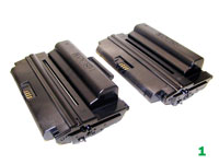
[1]
Place the cartridge with the handle/supply chamber facing you. Remove
the three screws on the right end cap. See Figure 2.
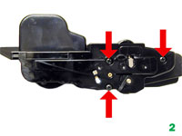
[2] Gently pry off plastic drum axle
bushing. Keep this bushing with the appropriate end cap when removed.
Each side is different. See Figure 3.
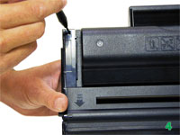
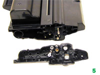
[3] On the top edge of the end cap, there is a
plastic tab. Press in on the tab and remove the right end cap. See
Figures 4 and 5.
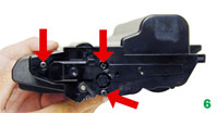
[4] On the opposite side of the cartridge,
remove the three screws on the left end cap. See Figure 6.
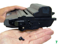
[5] Gently pry off plastic drum axle bushing.
Keep this bushing with the appropriate end cap when removed. See
Figure 7.
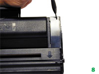
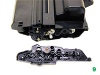
[6] On the top edge of the end cap, there is a
plastic tab. Press in on the tab and remove the left end cap. See
Figures 8 and 9.
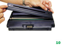
[7] Lift off the roller cover. See
Figure 10.
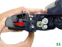
[8] Carefully pry up the side plastic tab to
release the waste chamber. See Figure 11.
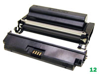
[9] Remove the waste chamber. See Figure 12.
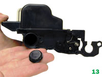
[10] On the supply hopper, remove the fill
plug and dump out any remaining toner. See Figure 13.
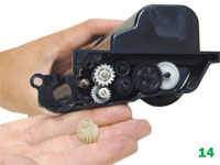
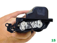
[11] Remove the developer roller drive
gear; put a strip of tape across the remaining gears. They do not need
to be removed; the tape will help keep them in place. See Figures 14
and 15.
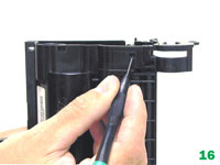
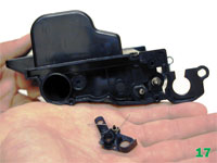
[12] On the fill plug side, press in on
the plastic tab and remove the spring/plastic bushing assembly. See
Figures 16 and 17.
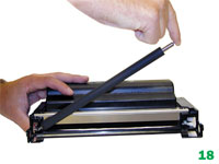
[13] Remove the developer roller. See
Figure 18.
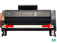
[14] Remove the two screws on the doctor
blade. See Figure 19.
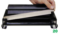
[15] Carefully pry up the doctor blade. This
blade has a very tight fit; work it off carefully. See Figure 20.
[16] Clean out any remaining toner from the
hopper.
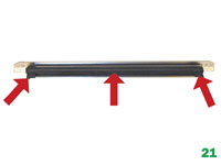
[17] Clean the doctor blade and foam seals. It is too
early to say exactly what chemical to use on the blade, but so far 99
percent isopropyl alcohol seems to work. See Figure 21.
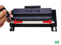
[18] Replace the doctor blade and two screws.
See Figure 22.
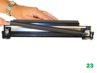
[19] Clean and install the
developer roller, long shaft side to gear side first. See Figure 23.
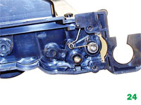
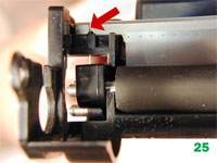
[20] Snap the spring/plastic bushing
assembly in place. Make sure the tail of the spring is set properly. See
Figures 24 and 25.
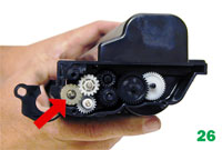
[21] Install the drive gear on the
developer roller. See Figure 26.
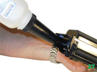
[22] Fill the hopper with 135g or 290g of
Phaser 3635 toner. Check for leaks. See Figure 27.
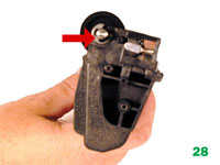
[23] On the waste hopper, remove the E-ring
from the drum axle. See Figure 28.
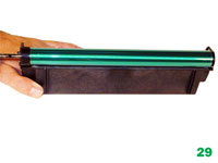
[24] Slide the drum axle out from the side
opposite the E-ring. See Figure 29.
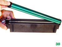
[25] Remove the OPC drum. See Figure 30.
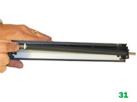
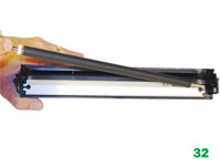
[26] Slide the PCR to the non-contact side.
Remove the PCR. See Figures 31 and 32.
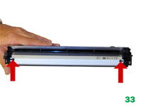
[27] Remove the two screws and the wiper
blade. See Figure 33.
[28] Clean out all the toner from the hopper.
It is interesting to note that on new cartridges, some toner is
in the waste hopper. Apparently these cartridges are being tested before
they are shipped, or the drum was lubricated with toner.
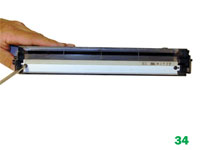
[29]
Coat the new wiper blade with your preferred lubricant. Install the new
wiper blade and two screws. The tail of the wiper blade should face up. See
Figure 34.
[30] Clean the PCR with your preferred PCR
cleaner.
WARNING: Do not clean the OEM PCR with alcohol, as this
will remove the conductive coating from the roller. If the PCR is an
aftermarket, follow the cleaning methods recommended by the
manufacturer. If the PCR is an OEM, we recommend it be cleaned with your
standard PCR cleaner.
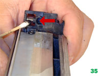
[31] Clean the old conductive grease off
the PCR shaft and contact. Replace with new. See Figure 35.
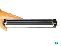
[32] Install the PCR by sliding the long
shaft side through the non-contact side. Bring it back to fit into the
contact side. See Figure 36.
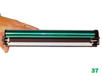
[33] Coat the OPC drum with your preferred
lubricant and install the drum. See Figure 37.
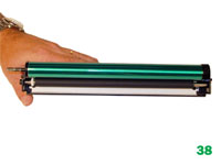
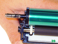
[34] Install the drum axle small drum gear
side first. Make sure that the E-ring groove ends up on the small drum
gear side. See Figures 38 and 39.
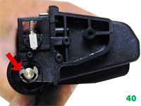
[35] Install the E-ring. See Figure 40.
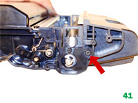
[36] Install the waste hopper on to the
supply chamber. Make sure that the tabs lock into place on the side
wall. See Figure 41.
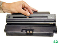
[37] Install the roller assembly. See
Figure 42.
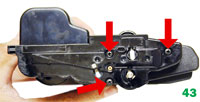
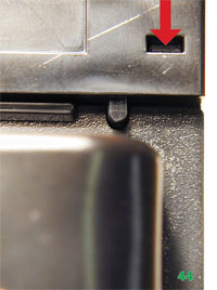
[38] Install the right side end cap and three
screws. Make sure the top rear tab locks in place. See Figures 43 and
44.
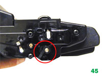
[39] Press the drum axle bushing in place. Set
it so the small tab is at the end of the groove; make sure it is fully
seated. The two small bushings are different. Make sure you have the
correct bushing for this side. See Figure 45.
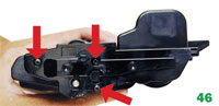
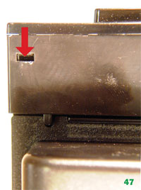
[40] Remove the tape from the gears, and
install the left side end cap and three screws. Make sure the top rear
tab locks in place. See Figures 46 and 47.
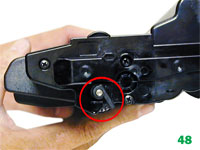
[41] Press the drum axle bushing in
place. Set it so the small tab is at the end of the groove; make sure it
is fully seated. The two small bushings are different. Make sure you
have the correct bushing for this side. See Figure 48.
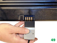
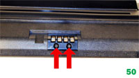
[42] The chip is held in place by plastic
rivets. It must be reset/replaced for the cartridge to work. Resetting
is the easiest method, (See Figure 49) but it can be replaced by
cutting the plastic rivets, drilling two holes, and setting two
self-tapping screws in place. See Figure 50.
Printing Test Pages:
As these
machines are copiers, the easiest way is to just make a copy of a
suitable test page.
 First released in August 2008, the
Xerox Phaser 3635MFP printers are based on a 35ppm, 1200dpi engine. The
first page out is rated at under nine seconds, and the monthly duty
cycle is up to 75,000 pages. Both model printers are print, copy, scan,
fax, and e-mail capable.
First released in August 2008, the
Xerox Phaser 3635MFP printers are based on a 35ppm, 1200dpi engine. The
first page out is rated at under nine seconds, and the monthly duty
cycle is up to 75,000 pages. Both model printers are print, copy, scan,
fax, and e-mail capable.