First released in November 2004, the Xerox Phaser 5500 is based
on a 50-ppm Xerox engine that runs at 1,200 dpi. These machines have a
monthly duty cycle of 150,000 pages and have a first page out in less
than eight seconds. They are heavy-duty network machines. If you have a
customer with one most likely they will be using quite a few cartridges.
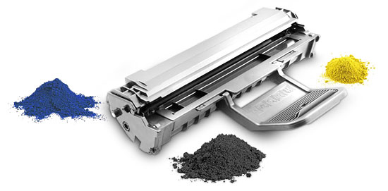
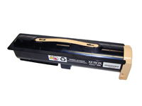
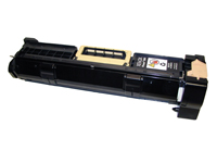
These machines are a bit different from most these days in that they
use a separate toner tank, and the drum unit also has developer in it.
The
toner cartridge (113R00668) is rated for 30,000 pages, and the drum
unit (113R00670) for 60,000 pages. While that is the "rated” spec for
the drum cartridge, in reality it is less. Rather than pages, the
machine counts drum cycles. There are a maximum number of cycles set at
240,000. The 60,000-page life is based on an average job length of six
single-sided pages.
The following is taken directly from the Xerox service manual:
"As an example of how job length effects the drum cartridge life count, a
continuous print job having a job length of 500 to 1,000 pages results
in a drum cycle count of 3.2 cycles per page. At 3.2 cycles per page,
the drum cartridge life count increases to 75,000 prints. However, if
the customer were to print mostly single-page jobs, the drum cycle count
increases to 7.8 drum cycles per page reducing the drum cartridge life
count to 31,250 pages.”
The reason for this is that there are
start and stop cycles. So what this means is the bigger the print jobs,
the longer the drum cartridge will last; the smaller the print jobs, the
shorter it will last. Considering the above information, it’s highly
doubtful anyone will get the stated 60,000 pages.
The stated
retail price (as of October 2007) for the toner cartridge is $154 and
the drum unit is $374. So as you can see, there is plenty of room for a
nice profit margin.
Current machines based on the Phaser 5500
engine are:
Xerox Phaser 5500B
Xerox Phaser 5500DN
Xerox
Phaser 5500DT
Xerox Phaser 5500DX
Xerox Phaser 5500N
As
this machine is a bit different from the norm in how it works (toner
and developer), we are covering the cartridge theory here as well.
Machine
and cartridge troubleshooting are covered at the end of this article.
Before
we go into the actual cartridge theory, lets go into what developer is.
Developer is actually made up of two components, metal filings
(carrier) and toner. When developer is manufactured, the correct toner
is mixed with the carrier at a specific percentage. As long as
everything is running correctly, developer never actually leaves the
cartridge. It picks up the toner from the supply chamber, brings it out
to be transferred to the drum, and returns to the developer section
where it will pick up more toner and start over again. A sensor located
in the toner/developer section of the cartridge controls the mixture of
the toner and developer. This sensor looks for a specific mixture. When
it does not see the proper mix, it will cause the machine to cycle and
bring more toner into the developer section until it does. That is why
with two-cartridge systems, when a new toner cartridge is installed it
will cycle for a while before it goes to ready.
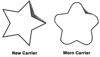
The best
explanation I have ever heard for why developer must be replaced is
this: think of a single metal filing as having the shape of a five-point
star. (It doesn’t but it makes it easier to explain.) When the
developer is new, the points of the star are sharp, and there is a
considerable amount of surface area between the points for the toner to
sit. As copies are run, the friction of the toner, other carrier
particles and the magnetic roller will start to wear the points down. As
the points get dull, the surface area for the toner to sit in
decreases. This will cause light prints and if let go long enough, the
toner-low sensor will never see the correct mixture and will not allow
the machine to go to the ready state. See diagram below.
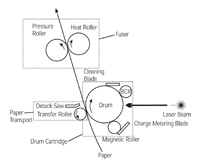
The toner cartridge printing process is best explained as a
series of steps or stages. See Figure 1.
In the first stage the primary charge roller (PCR) places a
uniform negative DC bias voltage on the OPC drum surface. The printer’s
intensity setting controls the amount of the negative DC bias placed on
the drum. This process is called conditioning.
In the second
stage (the imaging section) the laser beam is fired onto a rotating
mirror or the scanner. This printer actually uses a dual laser beam
unit, which helps speed up the scanning process. As the mirror rotates,
the beam reflects into a set of focusing lens. The beam then strikes
the OPC’s surface, leaving a latent electrostatic image on the drum.
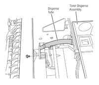
The third stage (developing stage) is where the toner
image is developed on the drum by the developing section. This is where
things change a bit for this system. As the magnetic roller in the drum
cartridge turns it picks up the developer, which has a full load of
toner on it. The toner is fed from the toner cartridge through an
auger/port system. See Figure 2. When the developer mixture sensor
senses the proper mixture, it sends a signal to stop the agitator and
the toner stops being fed into the drum unit.
The toner/developer
is held to the magnetic roller sleeve by the stationary magnet inside
the sleeve and a negative DC bias voltage supplied by the high-voltage
power supply. This DC bias voltage is controlled by the printer’s
intensity setting and causes either more or less toner to be attracted
to the drum. This in turn will either increase or decrease the print
density. The printer’s intensity setting controls both the PCR and
magnetic roller’s DC bias voltages. The amount of toner/developer on the
magnetic roller sleeve is controlled by the doctor blade, which uses
pressure to keep the amount of toner on the magnetic roller sleeve
constant. This blade also causes a static charge to build up on the
toner/developer, which helps keep the coating of toner even and allows
easy transfer to the OPC drum. (Xerox calls the doctor blade a "charging
and metering blade.”)
As the laser-exposed areas of the OPC drum
approach the magnetic roller, the toner particles are attracted to the
drum’s surface due to the opposite voltage potentials of the toner and
laser-exposed surface of the OPC drum. The charge differential is great
enough to attract the toner to the drum, but not great enough to pull
the developer. The developer stays on the magnetic roller and returns to
the hopper for more toner.
In the fourth stage (transfer stage)
the toner image is then transferred to the paper as it passes below the
drum by the transfer charge roller, which places a positive charge on
the back of the paper. This positive charge causes the negatively
charged toner on the drum’s surface to be attracted to the page. The
small diameter of the drum, combined with the stiffness of the paper,
causes the paper to peel away from the drum.
In the fifth stage
(separation stage) the paper separates from the drum. The static charge
eliminator weakens the attractive forces between the negatively charged
drum surface and the positively charged paper. This prevents toner
dropouts onto the paper at low temperatures and humidity. It also
prevents paper from wrapping around the drum.
In the sixth stage
(fusing stage) the image is then fused onto the paper by the fuser
assembly, which is comprised of the upper and lower fuser rollers. The
paper passes between a heated upper fusing roller and a soft lower
rubber roller that presses the page up into the upper roller. The upper
heated roller then melts the toner into the paper.
In the seventh
stage (drum cleaning stage) the OPC drum is cleaned. On average
approximately 95 percent of the toner is transferred to the paper during
the print cycle. As the drum rotates during printing, the remaining 5
percent of the toner that is on the OPC drum is cleaned off the drum by
the wiper blade. It is then guided into the waste chamber by the
recovery blade and stored in the waste chamber.
Once the print
cycle has been completed, the PCR will place an AC voltage across the
drum surface that erases any residual charges left on the drum surface.
The OPC drum is now ready to be conditioned by the PCR using the
negative DC bias voltage, and start the print cycle again.
1) Phillips-head screwdriver 2) Small
common screwdriver 3) Vacuum approved for toner
Remanufacturing
the toner cartridge
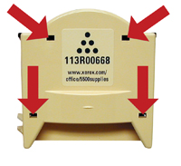
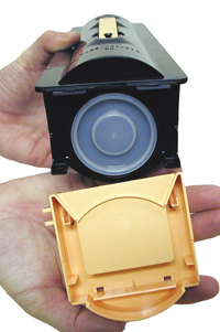
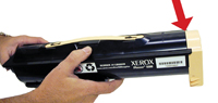
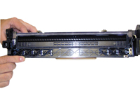
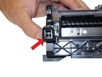
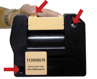
1) On the beige end cap, locate
the four small rectangular holes. In each of these holes is a locking
tab. With a small jewelers screwdriver, press up on the top two tabs to
release the top half, and press down with the screwdriver to release the
bottom half. Remove the end cap. See Figures 3 and 4.
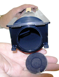
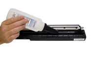
2) Remove the fill plug and clean out all remaining toner. See Figure
5.
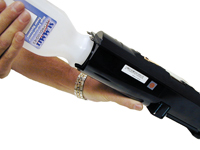
3) Fill with 500 grams of Phaser 5500 toner. Replace the fill plug.
See Figure 6.
4) Install the end cap. Make sure it fully snaps in place. See Figure
7.
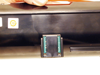
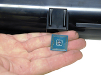
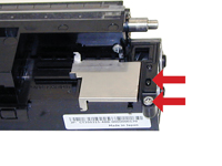
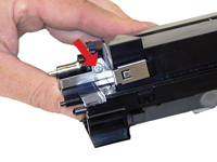
5)
Replace the chip by pulling up on the chip cover, lifting the chip up
slightly so it can slide over the two tabs. See Figures 8 and 9.
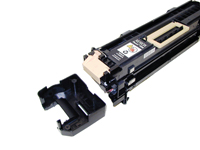
Remanufacturing
the drum cartridge
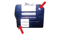
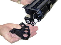
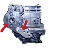
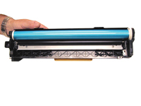
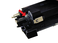
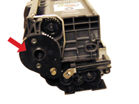
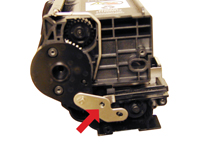
1) Remove the two screws located on the handle-side end cap.
Remove the end cap. See Figures 10 and 11.
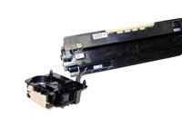
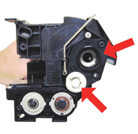
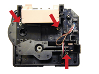
2) Remove the four screws from the inner end cap. Remove the end
cap. See Figures 12 and 13.
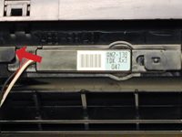
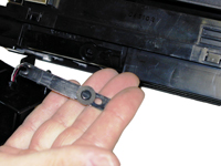
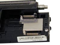
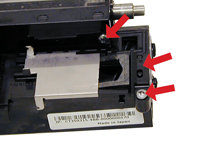
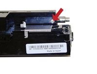
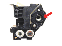
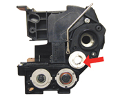
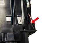
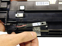
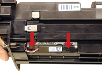
3) Follow the wires from the inner end cap to the sensor. Pry up on
the two locking tabs and remove the sensor. Place a small piece of tape
over the sensor hole. See Figures 14, 15 and 16.
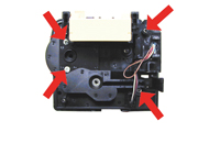
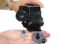
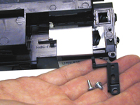
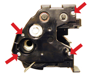
4) On the non-gear side, remove the three screws from the end cap.
Remove the end cap. See Figures 17 and 18.
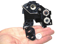
5) On the large-gear side, remove the metal plate and the drum
bushing. See Figures 19 and 20.
6) On the opposite side (non-gear side), pry off the white gear and
drum bushing. See Figures 21 and 22.
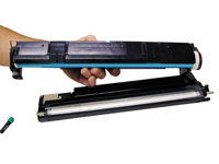
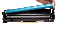
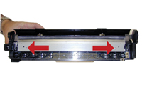
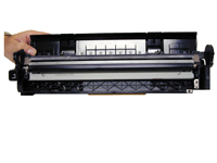
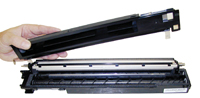
7) Carefully separate the halves. See Figure 23.
8) Remove the drum and place aside. See Figure 24.
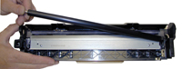
9)
Remove the PCR. See Figure 25.
10) Remove the two screws from the wiper blade. Remove the blade. See
Figure 26.
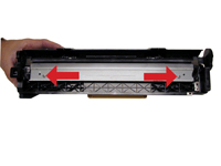
11) Clean out any toner from the hopper. Make sure you also clean out
the auger post. See Figures 27 and 28.
12) Install the
new wiper blade and two screws. See Figure 29.
13) Clean the PCR with your normal cleaner. Wipe off the old
conductive grease from the shaft and replace. Reinstall the PCR in the
assembly, grease side to the black PCR holder. See Figure 30.
14) Place the drum in the hopper and carefully place aside. See Figure
31.
15)
On the developer roller side, remove the two springs from the metal
slide cover. See Figure 32.
16) Remove the plastic spring arm and the two screws. See Figures 33
and 34.
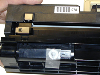
17)
Remove the screw from the contact plate on the opposite side of the
hopper. See Figure 35.
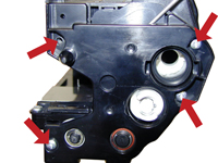
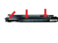
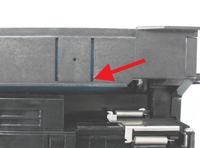
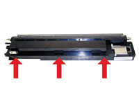
18) Carefully pry up the three plastic tabs on the back edge of the
cartridge. See Figure 36.
19) Lift off the cover and locate the chip. See Figure 37.
20) From the inside of the cover remove and replace the chip. See
Figure 38.
21)
Remove all the old developer from the hopper. See Figure 39.
22) Pour in the new developer. Make sure you cover both augers. See
Figure 40.
23) Snap the cover back in place. Make sure all three tabs lock. See
Figure 41.
24) Install the back screw in front of the metal cover. See Figure 42.
25) Install the plastic spring arm and the screw to hold it in place.
(Sliding the cover over allows the spring arm to fit correctly.) See
Figure 43.
26) On the opposite side, install the screw into the metal contact. See
Figure 44.
27) Install both springs on the metal cover. See Figure 45.
28)
While holding the halves together install the drum bushings, the
point-ed one to the gear side (with the metal plate) and the double
bushing to the non-gear side. Also install the white gear onto the keyed
shaft. See Figures 46, 47, 48 and 49 (from left to right then down).
29)
Install the end cap and three screws on the non-gear side. Make sure
the white gear fits properly. See Figure 50.
30) Install the inner handle end cap on the gear side, and the three
screws. Watch the wire routing so that they do not get pinched. See
Figures 51 and 52.
31)
While holding the cartridge so the developer will not spill out, remove
the tape from the sensor hole. Make sure the wires are routed correctly
and snap the sensor back in place. See Figures 53 and 54.
32) Install the
outer end cap onto the gear side and the two screws. Press down on the
handle to allow the end cap to fit properly. See Figure 55.
Cartridge
troubleshooting
No real problems have been noted so far. The
repetitive defect table is as follows:
Drum: 94.2mm
Upper
fuser roller: 78.5mm
Transfer roller: 58.7mm
Developer
roller: 56.5mm
PCR: 44.0mm
Machine
troubleshooting
As with most machines these days, the error
codes are in plain English and self-explanatory. There is no reason to
go into them here.
Mike Josiah is technical director at
Summit Technologies, a division of Uninet Imaging Inc., a global
distributor of toner, OPC drums, wiper blades and other supplies. Josiah
has been with the company since 1987. He and his technical support team
regularly contribute articles and teach seminars at association
meetings and trade shows. Contact Mike Josiah at 631-218-8376 or
mjosiah@uninetimaging.com.
 The third stage (developing stage) is where the toner
image is developed on the drum by the developing section. This is where
things change a bit for this system. As the magnetic roller in the drum
cartridge turns it picks up the developer, which has a full load of
toner on it. The toner is fed from the toner cartridge through an
auger/port system. See Figure 2. When the developer mixture sensor
senses the proper mixture, it sends a signal to stop the agitator and
the toner stops being fed into the drum unit.
The third stage (developing stage) is where the toner
image is developed on the drum by the developing section. This is where
things change a bit for this system. As the magnetic roller in the drum
cartridge turns it picks up the developer, which has a full load of
toner on it. The toner is fed from the toner cartridge through an
auger/port system. See Figure 2. When the developer mixture sensor
senses the proper mixture, it sends a signal to stop the agitator and
the toner stops being fed into the drum unit.